Occipital 10-10 montage¶
Eight electrodes over occipital and parieto-occipital cortex on standard 10-10 sites — P1 PO3 O1 POz Oz P2 PO4 O2 — wired to an OpenBCI Cyton, with reference and ground on the earlobes.
This is the toolbox's default montage. Every channel is a site the SSVEP literature already reports and every EEG cap already has a holder for, so the recording means something to a reader who has never opened this repository, and an analysis pipeline that knows the 10-10 system — including this toolbox's own occipital ROI (ssvep.spatial) — can name the channels without being told anything.
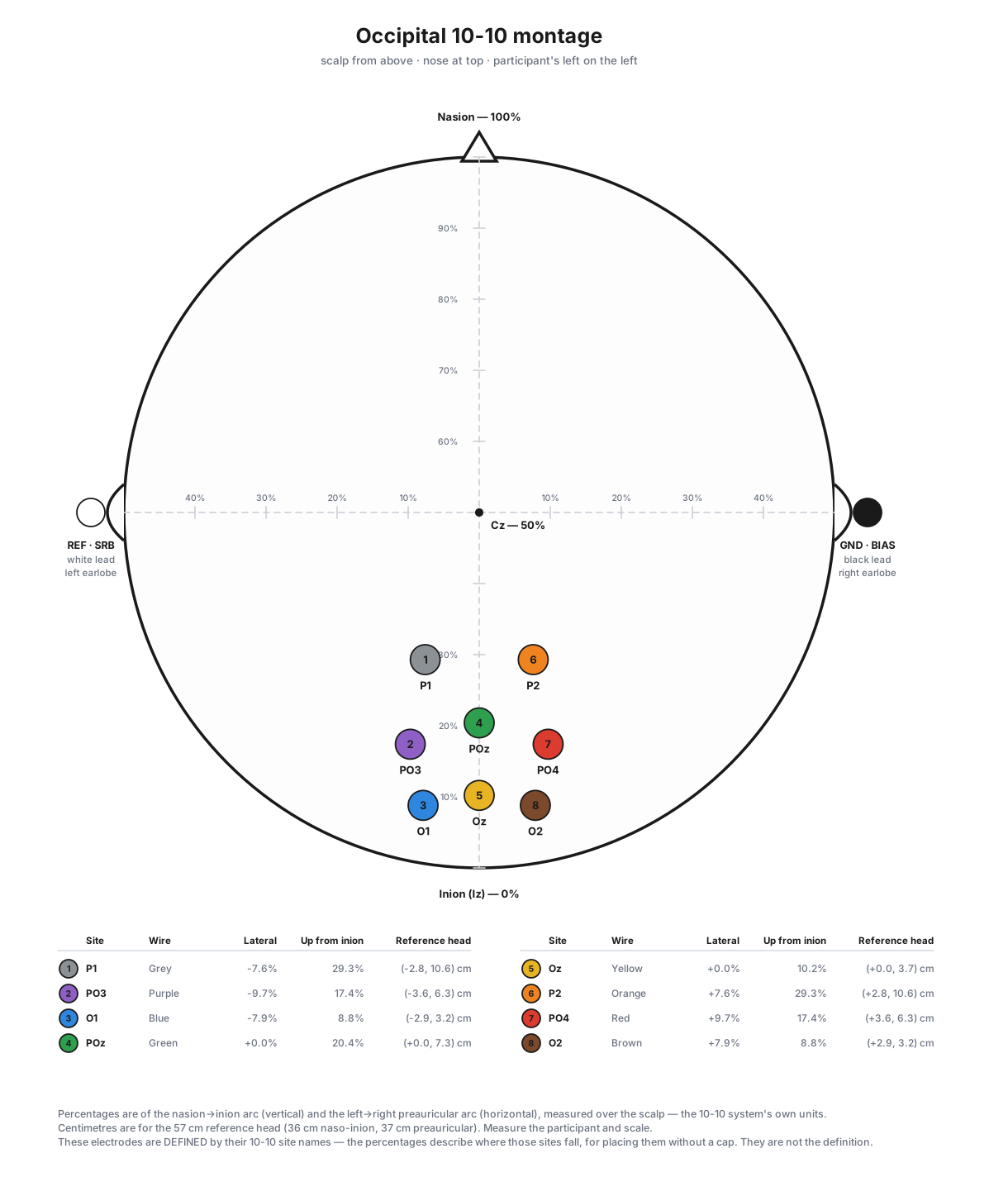
1. The montage¶
| Ch | Wire | Site | Lateral | Up from inion | 57 cm head |
|---|---|---|---|---|---|
| 1 | Grey | P1 | −7.6 % | 29.3 % | 2.8 cm left, 10.6 cm up |
| 2 | Purple | PO3 | −9.7 % | 17.4 % | 3.6 cm left, 6.3 cm up |
| 3 | Blue | O1 | −7.9 % | 8.8 % | 2.9 cm left, 3.2 cm up |
| 4 | Green | POz | 0 % | 20.4 % | on the midline, 7.3 cm up |
| 5 | Yellow | Oz | 0 % | 10.2 % | on the midline, 3.7 cm up |
| 6 | Orange | P2 | +7.6 % | 29.3 % | 2.8 cm right, 10.6 cm up |
| 7 | Red | PO4 | +9.7 % | 17.4 % | 3.6 cm right, 6.3 cm up |
| 8 | Brown | O2 | +7.9 % | 8.8 % | 2.9 cm right, 3.2 cm up |
Board order runs left hemisphere, then midline, then right. Channel colours follow the Cyton's ribbon cable (§3).
The site name is the definition — the percentages are not
PO3 already says exactly where the electrode goes. The percentage and centimetre columns are descriptive: they are where those sites fall on the nasion→inion and left→right preauricular arcs of the standard_1005 template head, computed by scripts/build_montage_figures.py for operators placing the montage without a cap. They are accurate to well under a millimetre on that template; on a differently-proportioned head the standard 10-10 construction and a tape-measure walk diverge a little, and the site name wins. That is why the toolbox records no position_pct for this montage — a second statement of the same fact is free to drift from the first.
The midline sites land where the 10-10 system says they should — Oz at 10.2 % and POz at 20.4 % of the naso-inion arc, against a definition of 10 % and 20 % — which is a useful check that the template and the arithmetic agree.
2. Placing it¶
With a cap — the intended route. Fit the cap by the usual procedure (Cz at the crossing of the nasion→inion and preauricular arcs) and put the eight electrodes in the P1 PO3 O1 POz Oz P2 PO4 O2 holders. Nothing else to measure.
Without a cap, mark the standard landmarks first: nasion, inion, the two preauricular points, and Cz where the two arcs cross at 50 % each. Then:
- Up the midline from the inion, mark Oz at 10 %, POz at 20 % and Pz at 30 % of the nasion→inion arc. (These three are direct 10-10 definitions.)
- O1 and O2 sit on the head's circumference — the ring through nasion, the preauricular points and inion — 5 % of that circumference to each side of Oz.
- P1/P2 and PO3/PO4 are 10-10 in-fills on the P and PO row contours: P1 is the first step out from Pz along the P row, PO3 the second step out from POz along the PO row.
- Failing that, the centimetre column in §1 is the tape-measure approximation — measure up the midline to the height, then out from that point.
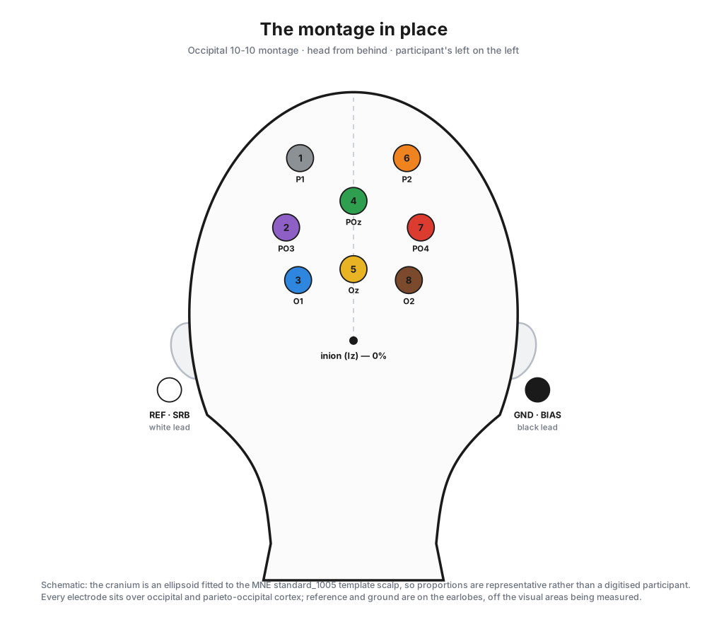
Reference and ground go on the ears¶
- Reference — the white lead, Cyton
SRB— on the LEFT earlobe (A1). - Ground — the black lead, Cyton
BIAS— on the RIGHT earlobe (A2).
Both are off the visual cortex, so neither carries much of the SSVEP being measured, and an earlobe can be placed identically on every participant without a measurement.
3. Wiring the Cyton¶
Channel colours follow OpenBCI's standard Cyton ribbon-cable order — 1 grey, 2 purple, 3 blue, 4 green, 5 yellow, 6 orange, 7 red, 8 brown. This is the board's convention, not the lab's: anyone who has wired a Cyton already knows it, and it is what the OpenBCI documentation shows.
| Pin | Wire | Goes to |
|---|---|---|
N1P |
Grey | P1 |
N2P |
Purple | PO3 |
N3P |
Blue | O1 |
N4P |
Green | POz |
N5P |
Yellow | Oz |
N6P |
Orange | P2 |
N7P |
Red | PO4 |
N8P |
Brown | O2 |
SRB |
White | reference — left earlobe (A1) |
BIAS |
Black | ground — right earlobe (A2) |
AGND |
— | analogue ground; nothing connects to it |
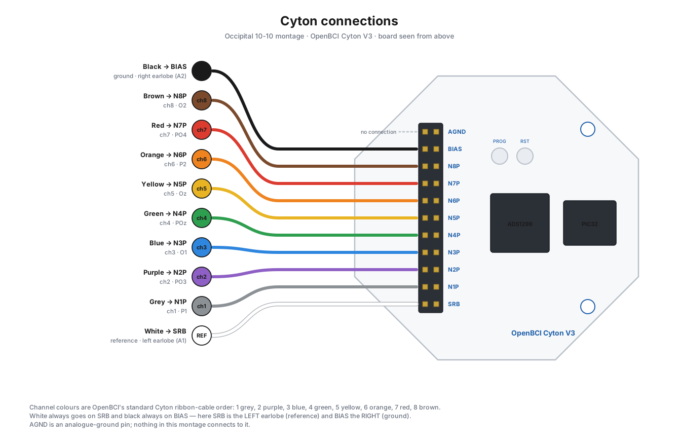
The eleven-pin header runs AGND, BIAS, N8P … N1P, SRB from one end to the other, so N1P is at the far end next to SRB. The board also silkscreens AVDD above the header and AVSS below it; those label separate two-pin sockets rather than positions on this header, and nothing here connects to them.
The reference pin is silkscreened SRB — one name, the one printed on the board you are holding. The header is a double row and we always use the row nearer the board, so the SRB1/SRB2 distinction in the ADS1299 datasheet never has to be made. Reference photo: OpenBCI's EEG setup page.
4. Where it sits in the 10-10 system¶
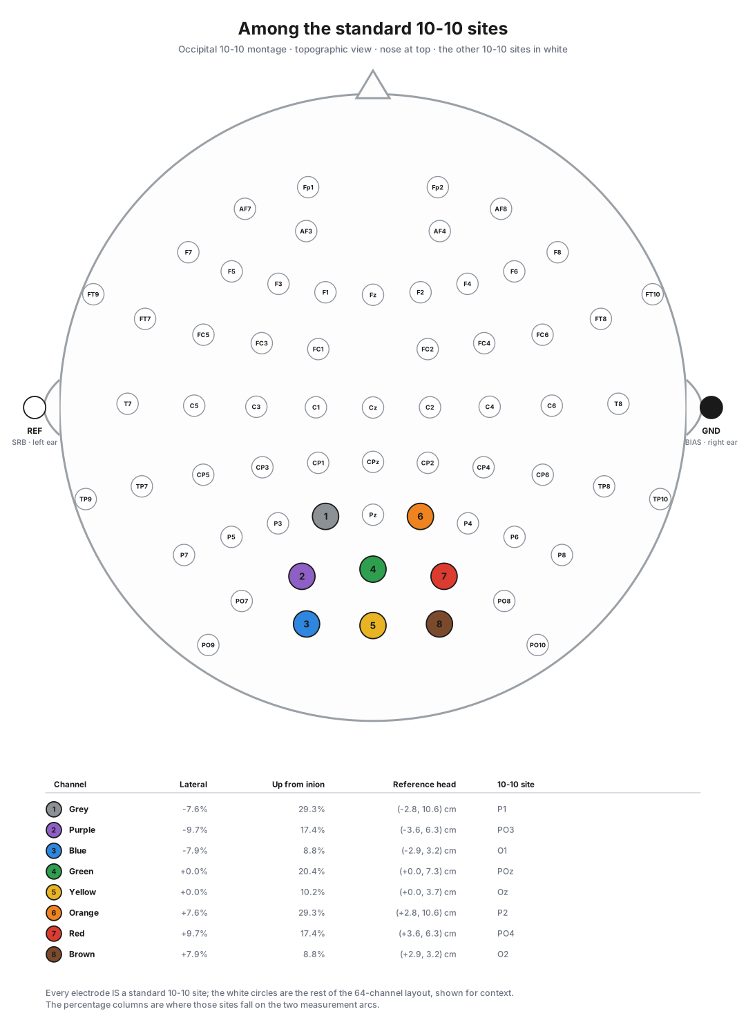
Every electrode is a standard site; the white circles are the rest of the 64-channel layout, for context. The eight chosen sites are the posterior core of this toolbox's canonical occipital ROI (ssvep.spatial.OCCIPITAL_PRIORITY) — so the decoder needs no special casing, and no channel is included that a standard occipital analysis would want to drop.
5. How the montage reaches the toolbox¶
| Thing | Where |
|---|---|
| The montage | builder.occipital_1010_montage() |
| Carrier name | builder.OCCIPITAL_1010_HEADSET — also builder.DEFAULT_HEADSET |
| The sites | builder.OCCIPITAL_1010_SITES |
| Wire colours | builder.CYTON_CHANNEL_WIRE_COLOURS |
| Reference / ground | builder.headset_reference_ground() |
In a recorded manifest each channel carries its site as its label, and a position_2d reused from builder.acticap_64ch_montage() so this montage and the 64-channel cap plot identically rather than drifting apart in two hand-typed tables:
There is no position_pct — see the note in §1.
It is selected by default on Build Protocol → Set up acquisition hardware, and can be corrected per session on Set up Session. Choosing it derives the electrode type (gold-cup (passive)) and the ear reference and ground automatically.
6. Regenerating the figures¶
The four SVGs in docs/figures/montage-1010/ are generated, not drawn. One run produces the figures for every montage the toolbox ships:
A figure drawn by hand would be a second copy of the montage table, and the second copy is the one that goes stale. tests/test_montage.py::test_figures_are_up_to_date_with_the_montages re-runs the script and fails if any figure changes.
Figures 3 and 4 need an actual head to draw on, so each site is placed on an ellipsoid fitted to MNE's standard_1005 template scalp and projected from there. The fitted ellipsoid and the projected 10-10 coordinates are baked into the script as constants, so it needs nothing but numpy — mne was used once, at authoring time, and is not a dependency.
If you need more density over the occipital pole¶
The 10-10 grid puts nothing between POz and PO3, so the closest this montage gets to the occipital pole on either side of the midline is a single pair of channels. The free electrode occipital SSVEP montage trades the standard site names for a tighter cluster there, and is what the lab's own pilot data was collected on. Its first section is the case for choosing it.
See also¶
- Free electrode occipital SSVEP montage — the denser, non-standard alternative.
- Impedance check — the Run-mode electrode check that plots this montage.
- Protocols and sessions — where the carrier is chosen and stamped into a run.
- BIDS conversion — where
referenceandgroundbecomeEEGReference/EEGGround.